1.10 Neumann Architecture
- ⭐️ fill in the gaps of the image
- ⭐️ all the names, and fill in the blanks
- ⭐️ fill in blanks of description and fill the blanks
- ⭐️ IR: what is inside each 4 portions, how it works
- first: operation, second: first num, third…
✅ Neumann Architecture
explains how the computer works inside
architecture of a computer
- This way of explaining architecture a computer has been valid since 1945
✅ 3 parts of computer in Neumann
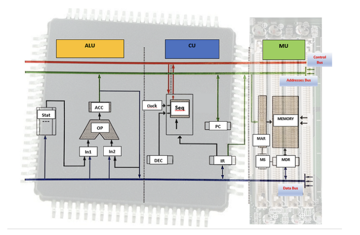
- ✔️ A - Control Unit: CU
- brain/boss of the computer
- give orders to the other units
- ⭐️ controls, sets the rythm/pace of the computer
⭐️ synchronizes the computer
- ✔️ B - Arithmetic-Logic Unit: ALU
- staff/workers of the computer
- ⭐️ part of the computer that really works/caculates
- use automatic gates
= logic gates
🏠 both CU and ALU are inside the microprocessor, CPU
- CPU: Central Processing Unit
- CPU =
CU+ALU 💡 and the
MUis inside the RAM- ✔️ C - Main Memory Unit: MU
- = RAM
- storing information, open process
- in a computer, secondary memory(harddisk) is not mandatory
- thus, in Neumann, we do not talk about secondary memory(harddisk) which is optional
- RAM is mandatory
📌 (A) Control Unit
sets the pace/rythm, controls and synchronizes the computer
- in a computer, process needs a fixed rythm/pace
❓ What would happen if a computer did not have rythm?
- without fixed rythm/pace, computer would be in chaos
- computer with no order would make an empty RAM
- 1️⃣ Empty RAM
- every process will take out information from RAM, but they will not have time to put information inside
- 2️⃣ Unevenly distributed data among process
- The data will not be evenly shared among the processes
- some process will take huge amounts, others will take very small prieces of data
- 3️⃣ Chaotic peripherals
- example: mouse that works both ways(input, output)
- the mouse is bi-peripheral(entering information and also showing information of where I am)
- wo a Control Unit, peripherals will not work properly
- when you don’t want to click, it will click, when you want to move, it will not move
❓ What happens when a computer has a rythm
- computers need a rythm
- 1️⃣ processes are organized
- 2️⃣ peripherals worked the way as intended
- 3️⃣ jobs get done
☑️ Two rythms of computer
- There are two rythms inside a computer
- each part of the computer chooose between two rythms
- 1️⃣ Clock: slow rythm
- example: standard hard disk: moves with plates
- reading from a harddisk, we read information as
clock based rythm
- 2️⃣ Micro-orders: fast rythm
- example: mouse
- mouse moves at
micro-ordersspeed
☑️ Internal blocks of CU
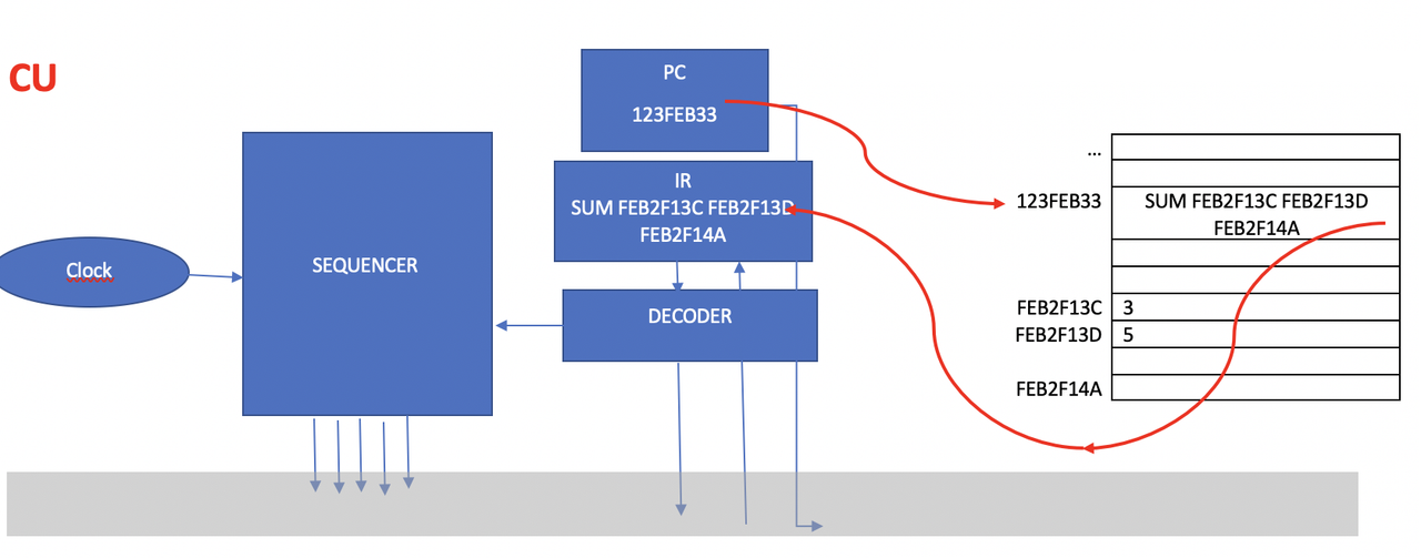
✔️ (a) Clock: block inside CU that creates the slow rythm/pace/signal in the computer
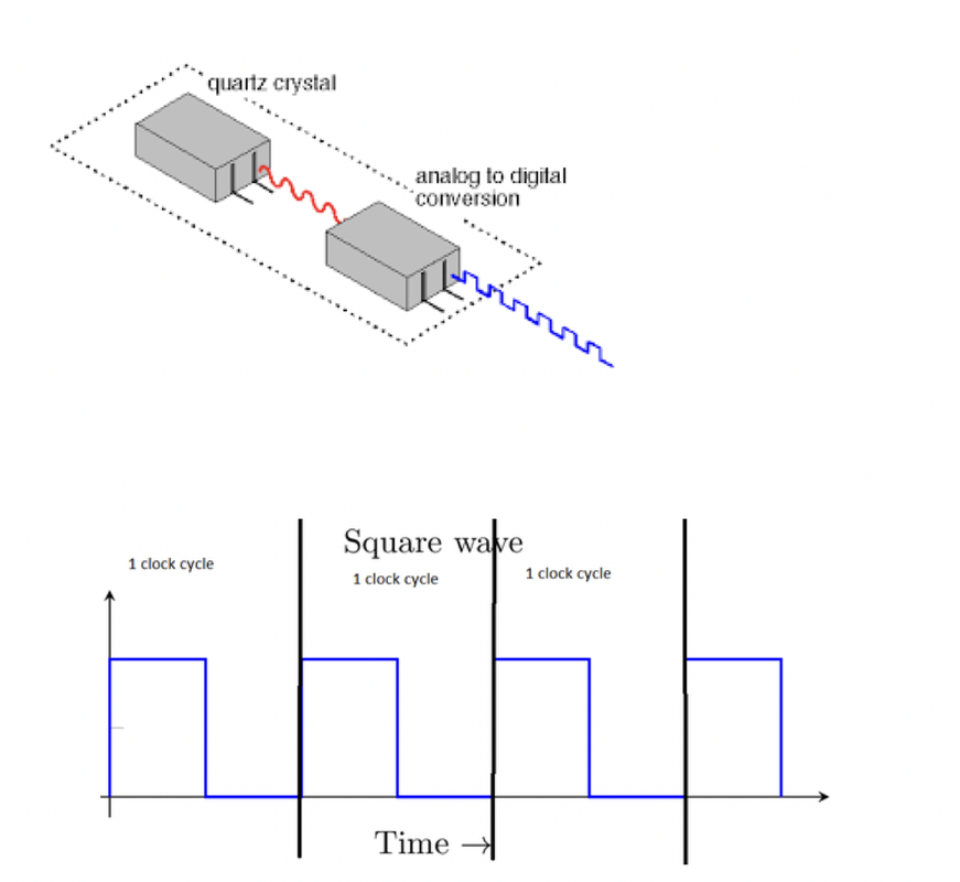
- tiny quartz crystal, looks like a tiny tiny cube
- so tiny that we do not see with eyes
- clock produces electricity without having to be plugged in
- produces a tiny wave automatically with several levels of electicity
- next to the clock, there is a block that converts the wave/radiation coming from a clock(looks like a wave) into a square radiation
- the square waves are simmilar to the ones of the power smaller
- this tiny square wave is not used to give electivity to other devices ❌
- this square wave is used to set the pace ⭕️
- In the transition from
0to1, that is one rythm when the clock makes a transition from
0to1, all the computer feels that transition- 💡 Clock can NEVER STOP
even if the computer is off, Clock does not stop
- in which the moment the clock is
1, is divided into portions - are the moments of
1are split into portions these small portions would be
micro-orders(fast)- Thus, after every clock stroke, there are some
micro-orders(fast)
✔️ (b) Sequencer: chip that divides the clock 1 to micro-order
- sequencer would create the
fast micro-order - ⭐️ Clock and Sequencer would create the slow and fast rythms for the computer
1
2
3
4
Program: when applications are closed and are stored on secondary memory
Process: when application is open, and are on RAM
- processes are fragmented, broken are into pieces and saved on RAM
- they are NOT saved continguously
✔️ (c) Program Counter
- block that contains the next address of the running process
- PC tells me where I can find the next portion of the process that I am running on the RAM
- somebody needs to tell me to look where to look next in the RAM
- as processes are fragmented and stored on RAM
- for addressing in RAM, we use hexadecimal
- ⭐️ thus the PC stores the hexadecimal address in which I am going to find the next instructions
- program counter does not tell me the instructions ❌
- program counter tells me where(address) to go to find the instructions ⭕️
✅ Indirect Addressing
This way of getting address is called: Indirect Addressing
- does not tell me the instructions
- but tells me where I can find the instructions
- 👎🏻 This indirect addressing slows the computer, as I have to get the address, go to RAM, come back…
- ❓ Why do we use indirect addressing?
- for security
much more secure bc the information is split/distributed among several components
- 💡 the addresses are called: Pointers
1
2
3
if PC: A2h
need to go to RAM address A2h
in address A2h, I will find the next instructions
- When I go to the address, I will find instructions in
4 portions - Instructions are always divided into
4 portions, has same length - When we take the
4 portionsof instructions, we will save them in Instruction Register
✔️ (d)Instruction Register
- save the
4 portionsthat I found with the help ofPConIR - Instruction Register will contain the
4 portionsof instructions that I found on the RAM - IR has 4 parts, one per portion
💡 Instructions are in 4 portions.
- Every instruction in computing is consited of 4 parts
- 1️⃣ Operation code:
- most of the operations are in the end mathematical operations
- exmaple:
SUM,SUBS(substracting),MUL(multiplying),DIV(dividing),SQT(square root)
- 2️⃣ Address of the First number:
- however, does not give me the number directly ❌
- will give me address of the RAM where I can find the first number
B3h⭕️ - also indirect addressing
- go to RAM
B3hand you will find the first number
- 3️⃣ Address of the Second number:
- give me the address of the RAM where I can find the second number
A5h - I need to go to
A5hin RAM to find the second number
- give me the address of the RAM where I can find the second number
- 4️⃣ Address of the result
- after making the caculation, I look at the 4th portion of the instruction
- and save the result at that address in the RAM
1
2
3
4
5
If IR is SUM B2 C3 E1
- add
- what you find in RAM address B2
- with what you find in RAM address C3
- then save the result in E1 in RAM
✅ 32 bits, 64 bits computer
- In a computer of
32bits, each of the addresses have32bits - 8 hexadecimal characters, example:
FFFFFFFFh - In a computer of
64bits, each of the addresses have64bits - 8 hexadecimal characters, example:
FFFFFFFFFFFFFFFFh - Thus, the
Instruction Registersis the longest stucture of the block
✔️ (e) Decoder
- helper/breaker for Instruction Register
- help the very long
Instruction Registerand break it into 4 portions
📌 (B) Arithmetic Logic Unit
in charge of making the caculations
- contains real data⭕️, not the address ❌
- real data coming from, or going to the RAM
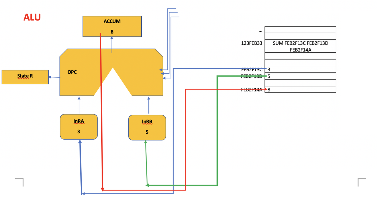
✔️ (a) Input Register A InRA
- contains the first number that comes from the RAM
✔️ (b) Input Register B InRB
- contains the second number that comes from the RAM
✔️ (c) Operational Circuit
- contains the logic gates
- does the math operations
- Operational Circuit used to be triangle, thats why has triangle in the middle
✔️ (d) ACCUM
- accumulator
- block that will accumulate the result before sending it to the RAM
- it is NOT a permanent storage ❌
- a temporal storage ⭕️
✔️ (e) State Register
- In some math operations, special things can happen
- what to do when special operations have to be run
- state registers contains 🚩 flags for each of the special operations that could happen
- If it is a normal operation, the state registers will be off,
example: 5+3=8 - however, if it is a special operation, state register will be on
example: caculation overflow! - example of special operation:
dividing by 0,5+5= 10 so we have to keep 0 and carry 1
🚩 We have 6 flags
- 1️⃣
Flag S: if sign flag is 1, result is negative number - 2️⃣
Flag Z: if zero flag is up, if the result is 0- in order to avoid dividing by 0
- ⚠️ so If flag Z is up, we should not divide! Divisions are controlled.
- 3️⃣
Flag V: overflow flag is up, when the result of the caculation exceeds than the possible number of bits managable by ALU - 4️⃣
Flag P: parity flag is1when in ECC error checking group, when the result of the subgroup is1, when I have to add1bc the number of1is odd - 5️⃣
Flag C: carry flag is1when I have to carry 1, like in1+1 = 10 and I have to carry 1 6️⃣
Flag I: Interrupt flag is1when there an interruption, when the anti-virus detects malware(all intrusions), the computer gets frozen, until the anti-virus quarantines the malware- Interrupt flag is also
1when high temperature is detected, to turn on the ventilator - so sometimes the ventilator is connected to the interrupt flag
- Interrupt flag is also
📌 (C) Memory Unit
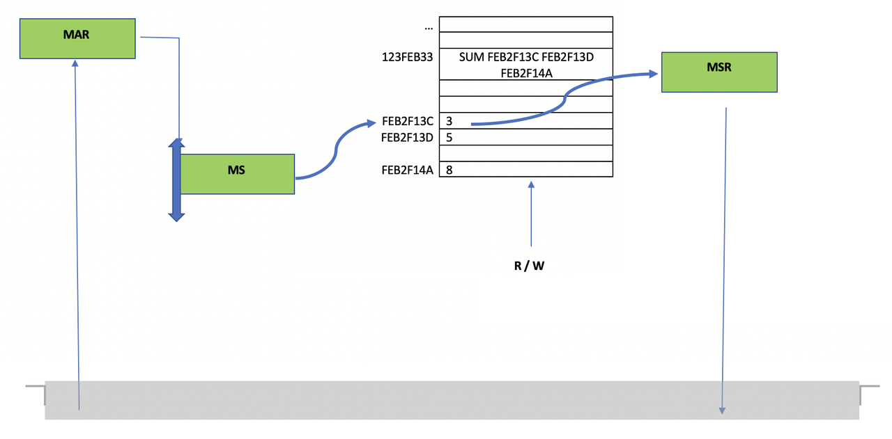
✔️ (a) Memory Selector
- Memory unit has an automatic selector(like an elevator) that is called
Memory Selector - that selects the level/address I want to reach
- it moves up and down the RAM and reaches the address
Memory Selectorcan go from00000000htoFFFFFFFFh- sometimes, if there is an error, the
Memory Selectorcan go to theOS areain RAM which is prohibited
✔️ (b) Memory Address Register MAR
- At the entrance of the RAM
- there is a block to check if the address we are trying to reach is 1️⃣ valid and 2️⃣ free
- checker of addresses
MARdoes not move, only lets entering RAM
✔️ (c) Memory Data/Swap Register MDR/MSR
- If the address is correct,
MARlets entrance to RAM Memory Selectorgoes up and down the RAM, and gets the information- and gives it to
MDR MDRis the delivery man of the data- takes the information in/out of the RAM
✔️ (d) Read/Write R/W
- like a flag
- This block has a value of
0if we read from the RAM - This block has a value of
1if we write inside the RAM
✅ Three Fixed paths
The transmission of information between different blocks always have to follow a fixed path
- All these paths are independent
1️⃣ Address Bus
- To transmit address among blocks, all the addresses travel along the address bus
- address bus is a set of wires
2️⃣ Data bus
- To transmit numbers among blocks, use the data bus
- to transmit the real numbers
3️⃣ Control bus
- All pace signals(
clockand themicro orders) travel through the control bus
✅ Bus
- when there is only one wire, bits travel by
serial,one by one,one behind the other - But if we have sets of wire(always set of 8)
- we say
"We have a Bus"(many wires) - 8 bits can travel at once
- bits go out in
parallel by groups of 8
- communication
serial: meansone by one - communication
parallel: meansby groups,by bus - 👍🏻 normally,
parallelis faster - 👉🏻 so in a neumann computer, we use
parallel, we usebus
⚠️ Exception of BUS
- is USB
- USB: Univeral Serial Bus
- in a USB, bits go by
one by one - Still USB is fast, bc of a high, fast cadency ⬆️
- cadency: speed of communication
📌 Instructions Cycle
how does a computer work?
Clockenters theSequencerSequencercreates the micro-ordersClockand micro-orders travels through thecontrol bus- A user would open a program
- Program is converted into a process
- The process is fragmented into fragments, and stored on the RAM, by
OS, This does not go through MAR/MS/MDR/R/W - In this state, RAM
R/Wwould be in write Program Counteris loaded with the address of the first instruction- This address travels through the
address bus - This address is shown to the
Memory Address Register, to be validated/if RAM is free - If valid,
Memory Selectormoves to the address - In this state, RAM
R/Wwould change to read - The 4 portions of the instruction is given to
Memory Data Register - The 4 portions of data travel through the
data bus - They arrive and are stored to the
Instruction Register - Fragment 1 travels through
data busand is given toOperating Circuitthat contains the logic gates, open gates are turned on - Fragment 2, the address of the first number, travels through the
address bus - This address is shown to the
Memory Address Register, to be validated/if RAM is free - If valid,
Memory Selectormoves/reaches to the address - Read the data in the address,
Memory Data Registergets the data - The data travels through the
data bus - The data is given to
Input Register A - Fragment 3, the address of the second number, travels through the
address bus - This address is shown to the
Memory Address Register, to be validated/if RAM is free - If valid,
Memory Selectormoves/reaches to the address - Read the data in the address, give the second number to
Memory Data Register Memory Data Registersends the data travels through thedata bus- The data is given to
Input Register B Input Register AandInput Register Bgive the data toOperating CircuitOperating Circuitdoes the caculationOperating Circuitgives the result to theACCUM- If there is no special operation,
State Rstays off - Fragment 4, address to store the result travels through the
address bus - This address is shown to the
Memory Address Register, to be validated/if RAM is free - If valid,
Memory Selectormoves/reaches to the address - In this state, RAM
R/Wchanges to write - The data from
ACCUMtravels through thedata bus Memory Data Registergets the information fromACCUM- So,
Memory Data Registerhas two roles, giving and recieving data - Until now,
Memory Data Registerhas been always extracting information from the RAM - but in step 38, recieves incoming information from the ALU
- So,
Memory Selectorreaches the address, then saves the data on the RAM- Next step,
Memory Address Registergets emptied Operating Circuitgets emptied- logic gates will be turned off
Program Counterwill now point to the next instruction, instruction 2, and every step will be repeated.
📌 Speed of the cycle
- This is the only way of making things organized
- without blocking the computer
as instructions keep coming
- All these 43 steps happen at the speed of clock of
2GHz,2000 000 000 times per second - computer has no brain
- it is just electric signs traveling